“G” Heat exchanger Module
The GRE “G” unit is a self contained, compact, atmospheric gas fired heat exchanger module incorporating a clam type constructed folded and welded heat exchanger with aluzink casing, and air tight compartment for the burner.
- Models 18 to 49 have 80mm air inlet and flue outlet collars
- Models 55 to 104 have 100mm air inlet and flue outlet collars
The “G” module has an integral flue fan which induces air into the unit and clears away the products of combustion. The excess air mix is such that the flue gas leaving temperature is no more than 120°C and single skin flue is generally suitable. The air inlet and flue outlet ends need to be in an equal atmospheric pressure zone which is best achieved with them in proximity of each other, similar to a typical flue dilution application. The module has an integral flue fan proving switch which sequences ignition after the fan has been established as working.
Where the module is fitted within an externally mounted Air Handling Unit, ideal flue conditions are achieved with either the fitting of one of the flue kit options described in the brochure or with a pair of pipes terminating with approved terminals at staggered heights above the unit.
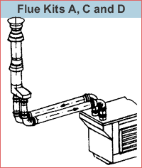
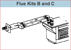
For internally mounted Air Handling Units or stand alone modules. The flue connection to the atmosphere with extended pipes available as kit C with the application of a horizontal or vertical “combi” pipe is ideal. Alternatively individual pipes terminating with approved terminals can be used. Once again the proximity of the flue outlet and air inlet terminal is important for balanced conditions.
The “combi” pipes shown as kits A,B,E,F & G can easily be cut to length to suit and the vertical units incorporate an outer sheath which can be cut to suit the storm collar supplied to make a weatherproof roof penetration. All the flue components are aluminium except for the high temperature plastic “connecting boot” which brings both pipes together for entry into the “combi” pipe.
Maximum Flue & Air pipe runs
| Models 18 to 98 | Flue run of 6 meters with two bends in each pipe (12m combined) |
| Model 104 | Flue run of 3 meters with two bends in each pipe (6m combined) |
If the runs need to be longer than the specified maximums, the diameter of the piping should be the next size up. For example: 80mm piping should be increased to 100mm and 100mm up to 130mm for runs of up to 12m (24m combined) on all appliances.
Flue Kits for Module type GT
| Flue Kit A | Vertical venting through roof of Air Handling Unit, or, with kits C & D vertical internal flue run to roof penetration. |
| Flue Kit B | Top flue/air collars with side discharge through Air Handling unit (either direction) or, with kits C & D, horizontal flue run to “through wall” outlet. |


Flue Kits for Module type GR
| Flue Kit E | Rear flue/air collars with options as kit B above. |
| Flue Kits F & G | Rear flue/air collars with options for left, centre or right for applications as A above. |
